|
BETONexpress,
software for designing structural elements of reinforced concrete. |
|
With BETONexpress you can easily
design structural elements of reinforced concrete. For each structural
element, you specify the basic dimensions, loads and material properties,
and you obtain the detailed concrete design in ultimate limit state
(ULS), and in serviceability limit state (SLS).
The dimensioning is according to Eurocode 2, EN 1992-1-1:2004,
Design of
concrete structures, General rules and rules for buildings, with
supplement of Eurocode 7, EN 1997-1:2004, Geotechnical design – General
rules, for geotechnical analysis (footings, retaining walls), Eurocode
0, EN 1990:2002, for load combinations, and Eurocode 8 for seismic
loading. The last EN versions of the Eurocodes are implemented.
You can also compute the capacity of slabs, beams and columns strengthened
with FRP (fibre-reinforced polymers). Regular and light weight aggregate
concrete included. |
|
The program's CAD modulus automatic generates detailed drawings of the
structure and the reinforcement. A combined detailed report and
reinforcing steel schedule is produced for the designed concrete
components. Assumptions and references to design codes are shown in the
report. The reinforcing steel schedule can be edited with a specialised
editor which is included. The user can select the applicable National
Annex. The design code parameters, as well as default values, can be
adjusted by the user. Design Charts and Tables for use and understanding
of Eurocode 2 are included n the program. In addition a set of
engineering tools are included in the program. |
|
New features in BETONexpress 2015 |
|

 |
 Slabs
SlabsSolid slabs and
ribbed slabs.
- Uniformly distributed dead and live loading.
Load combinations according to Eurocode 0.
- Two way slabs with various support conditions.
Czerny, Bares or Marcus solution methods.
-
One-way
continuous slabs (up to eight 8 spans). End cantilevers can be specified.
Load
factors for every span.
Moment
redistribution.
- Cantilever slabs.
- Crack and deflection control.
- Regular and
Light weight concrete.
-
Moment capacity of concrete slab
cross-sections and sections strengthened with FRP (fibre-reinforced polymers).
-
Flat slab, Punching shear
-
Flat slab design
|
 |
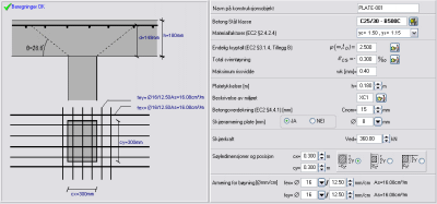
 Beams
Beams
-
Beams of rectangular or T section in combined
loading bending shear and axial force.
-
Beams of one span under combined loading.
- Continuous beams (up to 8 spans) under
uniformly distributed loading, combined loading bending, shear and torsion.
- Crack and deflection control.
- Regular and
light weight concrete.
-
Computation of moment capacity of concrete
beam cross-sections and sections strengthened with FRP (fibre-reinforced polymers).
|
 |
 Columns Columns
- Biaxial bending, (rectangular and round
section) isolated column (stability control). Second order effects.
- Biaxial bending (N-Mx-My) diagrams
obtained by numerical integration of concrete and steel forces over
the cross-section.
- Computation of moment capacity of
concrete column cross-sections and sections strengthened with FRP (fibre-reinforced
polymers).
- Complete Charts for simple and double
bending.
|
 |
Foundation bearing
resistance
(2015)
-
Soil bearing resistance
-
Drained and undrained conditions
The basis for the design of foundations is
the bearing resistance of the soil.
The design bearing resistance can be calculated using analytical or
semi-empirical methods. Annex D of Eurocode 7, EN1997:2004 describes a
method of obtaining the design bearing strength of the soil. |
 |
 Spread footings Spread footings
- Centrically loaded footings.
- Eccentrically loaded footings, and eccentric
footings.
Vertical loading and moments at the top. Dead
and live loading.
Exact computation of pressure distribution
under the footing. Geotechnical design using Eurocode 7, EN 1997-1:2004, or allowable soil
stress.
Load combinations according to Eurocode 7
(EQU, STR, GEO load cases), and Eurocode 0.
Full CAD drawing of footings with
reinforcement.
Fundaments of Steel columns
(2015)
The concrete footing of steel structures
has to be designed to resist soil pressure for maximum vertical load and
it must have enough weight to resist uplift from wind or seismic
forces.
You can design Pin and Fixed end column foundations.
You can also specify if the foundation has a horizontal tie to take the
horizontal outwards forces or not. |
 |
Loading on the fundament
The final actions after multiplication with safety factors (γG
and γQ) Eurocode-1990-1-1, Table A1.2
For downwards loading usual values are:
γG =1.35
(unfavourable), γQ=1.50.
For
upwards (uplift) loading usual values are:
γG =0.90
(favourable), γQ=0.00.
|
|
|
Steel Tie and Passive earth
pressure
The high horizontal forces acting at the
base are acting outwards as a result of bending in the columns due
to vertical loading on the roof. This is resisted in two ways.
-
Steel tie at column base
-
Passive earth pressure on the
side of the foundation
|
 |
 Retaining walls Retaining walls
Retaining walls of gravity or cantilever type
(reinforced). Geotechnical design using Eurocode 7, EN 1997-1:2004, Geotechnical design
– General rules or allowable soil stress. Active and passive earth pressure
using Coulomb's theory. Design of gravity walls using Eurocode 6 (EC6) or allowable
stresses.
Earthquake analysis according to Eurocode 8 (EC8), Mononobe-Okabe.
Two different types of cantilever walls in the program:
- Type-A. Walls with very small back heel. The
active earth pressure is computed using Coulomb's theory at the back face of the wall.
- Type B. Walls with back heel. The active earth
pressure is computed using Rankine's theory at a vertical surface at the end of the heel.
The design of cantilever type walls is based
on Ultimate Limit State Design of concrete according to Eurocode 2. The design checks are
performed at each tenth of the stem height. The reinforcement of the stem is optimised,
and depending on the stem height the reinforcement is reduced toward the top of the wall.
The reinforcing bars are automatically placed in the reinforcing bar schedules. Optional
Base
key against sliding.
Load combinations according to Eurocode 2,
Eurocode 7, (EQU, STR, GEO load cases) and Eurocode 0.
Full CAD drawing of retaining walls with reinforcement. |
 |
Water basins, swimming pools
(2015)
Design of rectangular water basins.
The solution is for a 2-dimensional cross section across the
smallest dimension (width) of the basin.
The basin is assumed to sit on elastic
ground and is analyzed with finite element analysis. The basin walls
are subdivided in 2 beam elements of length H/2.
The basin
floor is modelled with 16 beam elements with nodal points connected
to the ground with elastic springs. The
stiffness of the elastic springs is computed from the Winkler’s
foundation modulus Ks [kN/m2/m].
The loading conditions include all the load cases according to
Eurocode 0 (EQU, STR and GEO) for:
· Empty water basin (only earth pressure)
· Filled water basin without earth pressure
· Filled water basin with earth pressure
The reinforced concrete
design includes also serviceability control with limit crack width
specified by the user. |
 |
Basement walls (2015)
·
Walls with only the bottom restrained for lateral
movement.
·
Walls with restrained the bottom and the top for lateral movement.
In the first case the sliding of the wall is prevented due to
the retraining of the base in movement. The active earth pressure is
computed as usual using Coulomb’s (1776) or Rankine’s (1857) theory,
Eurocode 7 § 9.5.1.
In the second case, the active earth pressure conditions are
obtained for Ko in rest conditions according to Jaky (1948), Eurocode 7
§ 9.5.2.
|
|
Basement walls (2015)
Bearing walls in vertical or horizontal load on the top without any
earth pressure.
The horizontal load on the top can be defined
from Eurocode 1-1-1:2001 Table 6.12 according to National Annexes.
The horizontal load on the top can be also defined according to
Eurocode 1-1-7:2006, in case of impact load. |
 |
Walls with horizontal
distributed load (2015)
In case of wind loading the wind pressure is according to Eurocode
1-1-4:2005. |
 |
 Corbels
- BracketsShort cantilevers projecting from column faces, with
ac/hc<=1, where ac the load lever arm and hc the corbel height.
Design according to Eurocode 2, § 5.6.4,§ 6.5,
and Annex J.3. Load combinations according to Eurocode 2 and
Eurocode 1. Corbels
- BracketsShort cantilevers projecting from column faces, with
ac/hc<=1, where ac the load lever arm and hc the corbel height.
Design according to Eurocode 2, § 5.6.4,§ 6.5,
and Annex J.3. Load combinations according to Eurocode 2 and
Eurocode 1.
Full CAD drawing of corbels with
reinforcement. |
 |
 Deep
beams
Deep beams with dimensions Leff/h<=2, where Leff
length and h height.
Design according to Eurocode 2,
§ 5.6.4,§ 6.5, using simple strut and tie model. You can design deep beams subjected to
uniformly distributed load (with dead and live components) at the top and bottom faces of
the beam. Deep
beams
Deep beams with dimensions Leff/h<=2, where Leff
length and h height.
Design according to Eurocode 2,
§ 5.6.4,§ 6.5, using simple strut and tie model. You can design deep beams subjected to
uniformly distributed load (with dead and live components) at the top and bottom faces of
the beam.
Load combinations according to Eurocode 2, and Eurocode 0.
Full CAD drawing of deep beams with
reinforcement. |
 |
 Reinforced
concrete design charts Reinforced
concrete design charts
- Tables and Design charts with Eurocode 2 as: Kd , med w, effective length
- Design charts for column design single and double
bending.
- Design charts for deflection control
|
  |
 |
 Steel
bar
Schedule Steel
bar
ScheduleDetailed steel
bar schedule. You can modify and update the steelbar schedule simply with an editor,
with ready steel bar menus.
The report and the steel schedules can
also be exported to PDF and WORD files.
|
 |
 Preview
and print Report Preview
and print ReportFull report preview. The reports are very
analytical, showing all the computations, graphics, with references to the design
code paragraphs. The computational errors, or inadequate dimensioning, are shown in red.
- Export of all reports to PDF or Word format.
- Export of all CAD drawings to PDF or
DXF(Autocad) format.

|

|
National
Annexes
Parameters
Design Rules
You can select the National Annex.
The code parameters, as well as default
values can be adjusted by the user.
- Users manual included in PFD
format.
-
On line help
A complete on line help assist the user for
the required data, as well as references to the corresponding code subjects, as well as
theoretical overview. |
 |
 Engineering tools
- Unit conversion
- Area calculations
- Section of properties
- Calculation Rolled steel shapes
- Reinforcement tools
- Anchorage lengths
- Earth pressure coefficients
|
 |
| Download free trial
version of BETONexpress |
|
| Revised:
juni 07, 2023. |